So Pelican batteries… those are cool. I’ve been building one off and on for the past 3 months. And this blog post is WELL over due. Sorry for the delay. In early January it looked like this article was actually gonna be sponsored by a 18650 company so the video that was being edited was deleted because we’d have to reshoot everything but this time with the companies 18650 cells in the photos. Well that didn’t happen. emails dried up when it got closer to reshooting the video. All that survives from January is a still image from the original video shoot.

And it was a good video too. It had music and white board graphics that are so popular with the kids on the interwebs. But sadly it’s gone, never to be seen. And since then I have upgraded MacOS to High Sierra and FCP7 is no longer supported so new videos will take a step back to old fashion DIY blog post. Let’s get started.
*****CAUTION: Lithium Cells discharge A LOT of amps when you accidentally short them out and can cause flammable material to instantly burst into flame. During this project watch out what you place raw cells on and make sure things like iron filings, loose strains of wire, or metal in general does not come into contact with the tips of your 18650s unless you mean to solder that metal to the tip. As you solder your battery pack double check the polarity of your cells at all time. Stay VERY organized. Also remember you are soldering electrical items that are carrying a charge at all times, wear latex gloves to help prevent being shocked and burned. Use pliers and flush cutters with rubber handles. Be Safe******
Itemed Needed:
A Bunch of 18650 Cells: (Pick 1)
- Here are some links to purchase bulk cells at HEAVILY reduced prices (March 2018 Links)
LG 2600mAh – ~$1.35cell – Some tech labor required to break open plastic shells but its the BEST deal for the capacity: https://www.ebay.com/itm/99-LG-18650-2600MAH-LGABB41865-CELLS-LITHIUM-ION-BATTERIES-POWERWALL-EBIKE-EV/202227213667?hash=item2f15ae6563:g:jbwAAOSwg8taKuC7 - Samsung 2600mAh ~ $1.40 cell – Some tech labor required to break open plastic shells but its a good deal for the capacity: https://www.ebay.com/itm/99-SAMSUNG-18650-2600MAH-ICR18650-26F-CELL-LITHIUM-ION-BATTERIES-POWERWALL-EBIKE/173220714149?hash=item2854c256a5:g:MxkAAOSwnBJarEKz
- Generic 2000mAh ~ $1 cell – Comes already as loose single cells: https://www.ebay.com/itm/50-1801-2000mah-MOLICEL-18650-ICR18650H-CELL-LITHIUM-ION-BATTERY-POWERWALL-DIY/173223651996?hash=item2854ef2a9c:g:RHEAAOSwxnVanZCj
- Pre-Built 20,000mAh 12.6 Lithium Ion Battery Pack of 18650 cells. If you can only solder an XLR cable and not much else, this is the route for you. You could fit 2 of these into a small hard case if you wanted a mega battery: http://amzn.to/2IHB3VM
3S BMS PCB circuit: This will do the all the thinking and processing when it comes time to solder the 18650 cells. You do not need a 3S BMS PCB board if you choose the route of buying a Pre-built 20,000mAh pack.
12.6V Lithium Charger
- http://amzn.to/2FYxMzD – This is no ordinary DC power adapter. It monitors the load to also indicate if its pushing power through or if the BMS circuit has cut it off to protect from over charging the cells. It’s also a 2 phase charger to make sure your cells are charged all the way up to 4.2V each.
Small Pelican Style Case

- I used the Harbor Freight 1800 Watertight Case. It’s a pelican knock off for $14.99 (coupons will reduce it to $9.99) and it works VERY well. I reviewed the case HERE. If you want to buy a real Pelican case go ahead… we will be violating the f*** out of the lifetime warranty though. https://www.harborfreight.com/1800-watertight-protective-case-9-316-in-63518.html
- If you are looking at the Pelican 1120 for $30 you can see that the Apache 1800 is larger by alot. It’s even a little taller than the Pelican 1200 at $40. The Apache 1800 really is the best deal for a DIY project.
4 Pin XLR – Male and Female (You need all 3 below)
- Female Panel Mount – http://amzn.to/2puzRNi
- Male Panel Mount – http://amzn.to/2FZ2ZCu
- Female Cable Connector (To put a new connector on the charger) http://amzn.to/2Gan0JF
LED Battery Meter (Pick 1)
- Battery Meter that will display how much battery you have left – http://amzn.to/2G8WtwC
- “Luxury Model” voltage display that will also calculate your current amp draw and energy used. but won’t tell you how much of your battery is left unless you memorize your voltage cutoff and cell curves (not for newbs) – http://amzn.to/2psBLxY
- Basic 3S Lithium Battery Display showing remaining capacity. Requires a 3D printer to finish it off with a bevel – http://amzn.to/2u6e7w3S
Standard WavReport Workbench Tools:
- Dremel – http://amzn.to/2ppfQb5
- Basic Soldering Iron Kit – http://amzn.to/2HSJMDb (A nicer kit would be nice, but this is a pretty simple soldering job that doesn’t require alot of fancy soldering gadgets)
- Flush Cutters – http://amzn.to/2IG4B6e (Actually this is my favorite flush cutter on the market. I have 3 that I keep in different tool boxes depending on the task I’m doing.)
- Soldering Helping Hand – http://amzn.to/2DH377W
- Drill – https://www.harborfreight.com/18-volt-38-in-cordless-drilldriver-with-keyless-chuck-21-clutch-settings-62868.html (Yes I know this cordless drill sells for $15 with a coupon at Harbor Freight but we are cutting into plastic using a Titanium drill bit… even a $15 drill will eat plastic all day.)
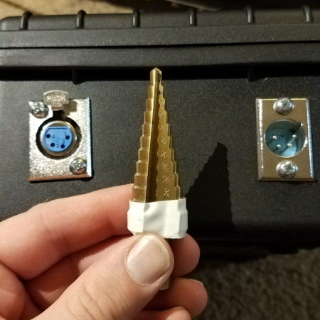
- Stepping Drill Bit- https://www.harborfreight.com/2-piece-titanium-nitride-coated-high-speed-steel-step-drills-96275.html
STEP 1:
Drill your holes into your case. For Neutrik D Series you will want to drill a whole 24mm or 7/8 Inch.

I used some electrical tape to mark my depth on my stepping drill bit for my second hole because the Switchcraft 4pin XLR is slightly narrower. It only required a 3/4” size hole.
Step 2:
With a black sharpie and a metal ruler draw out where your LED meter will sit. Drill out 4 pilot holes in your corners and use your Dremel to cut out the rectangle. Try your best to cut inside the line, you can always grind the hole open if you need too but you can’t add plastic back. I knew I would be 3D printing labels and a large faceplate. If you do find that you need to open up your hole more you can use the grinding blade on your Dremel or a flat metal file will work also.

Step 3:
Solder your leads to your connectors. Make each lead about 10-12” of wire. This will be more than you need but it will make positioning stuff easier during assembly.

Step 4:
***UPDATE: If you bought the already built 20,000mAh pack just solder a 2.1 Male DC plug to some wire and follow the wiring steps form P+/P- , you can ignore the talk about columns, rows, and B-pads on the BMS board, your 20,000mAh pack already has all that done***
Wire Up your 18650s into rows and columns. Here is a block wiring setup. I found it best to have the XLR panel mounts installed in the case when wiring the Battery Meter jumpers to the right pins.

Each “column” of cells is wired to the next and to the next in a series. All the cells in a single column are wired in parallel to each other, this determines the batteries capacity. Each column MUST have the same number of cells, otherwise the battery will default it’s capacity to which ever column has the least amount of cells. The number of “rows” of columns a battery pack has determines how big a battery pack is. The above block wiring setup displays 27x 18650 cells wired in what is called a 3S9P setup. 3S refers to how many cells make up the series, in this case 3. A traditional IDX-NP1 and Inspire Energy/Hi-Q battery is a 4S battery but is only 3P. The 3P in an NP1/Hi-Q battery refers to the fact that those battery packs only have 3x 18650 cells in parallel. To determine the capacity of a battery you take the cells individual capacity and multiply it against the number of cells in parallel. This pelican style battery can be as big or as small as you want, as long as you have room inside the case. If you bought the Apache 1800 case I estimated you could fit 48 cells inside of it for a 4S12P setup. For the battery I built I stuck with a 3S9P setup but opted to use some 3000mAh 18650 cells that I reclaimed from some brand new lithium cordless drill batteries.


Now I know the big block wiring setup can be confusing so I will show you on a smaller setup what you need to worry about when you wire up your battery.
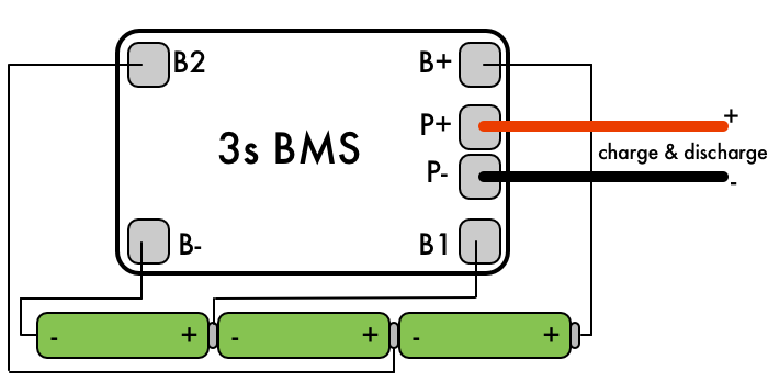
- B- = Zero Voltage. This is the negative terminal where your battery pack starts
- B1 = 3.7v. At this point in your battery chain you are really only messaging “1” group of cells. In this photo that actually means only 1 cell. But if you had 9 cells in parallel they still would only measure out to 3.7v nominal but instead would have a combined capacity.
- B2 = 7.2v. This wire measures the voltage of 2 cells in series. And the IC chip on the BMS board subtract the voltage measured at B1 against B2 to determine this individual groups voltage. This is how the BMS balances out each group of cells against the other groups so that 1 group’s voltage doesn’t dip out of control. The better matched your over all pack’s cells capacity is the more balanced and thus more predictable your pack will behave. Running test and checking each cells capacity before building your pack is called bottom balancing, the idea being when you get to the end voltage on the bottom side of your pack that 95+% of your cells are all spent and you don’t have a bunch of cells that are still holding onto juice that can’t be used anymore because you’ve reached the packs overall cutoff voltage. Unlike NiMH and Akline that will continue to putout even a small charge after they are considered “dead” a lithium pack using a BMS will output zero volts because the BMS circuit has a cutoff voltage to protect the cells form dipping below 2.75v per cell and some BMS boards will cut off that voltage even higher.
- B+ = The same as B2 but it is measuring the last cell in the series. This goes for all BMS boards no matter how many series they allow. You can have BMS boards that go up to 10S and the last one will always be marked as B+. B+ will also have the same voltage as P+ and on some boards be a substitute for P+ if the data sheet says so.
- P-/P+ = This is your main output and neutral/return. The voltage of P+ is the combined voltage of the series.
Now look at our original diagram again for our pelican style battery pack.

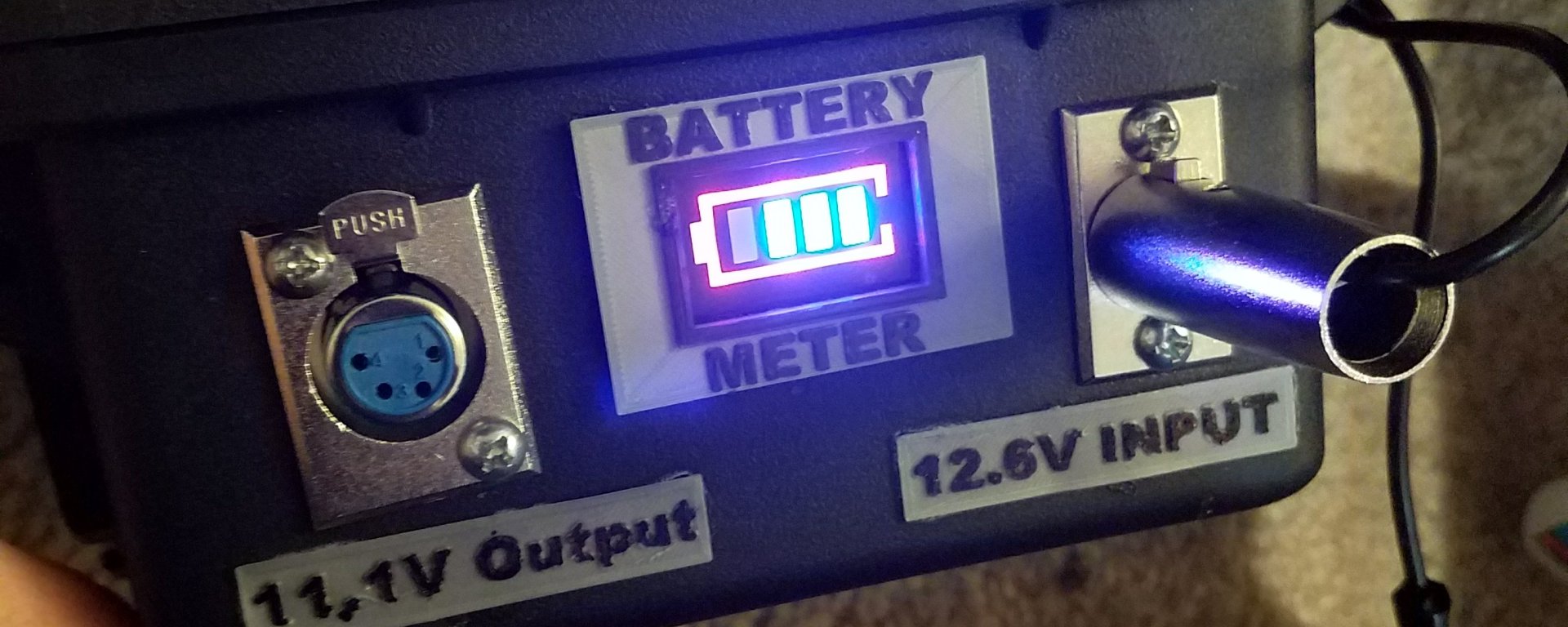
Notice that P+ goes to Pin 4 on both of the XLR connectors and P- goes to Pin 1 on both of the XLR connectors. This is standard across all film equipment that uses 4 pin XLR for power. For my build I wired the positive terminal of my battery meter to Pin 3 on both of my XLR ports. I researched high and low to determine if Pin 3 is used in any 4pin XLR power ports and if using this pin would cause any conflicts. To the best of my knowledge (and thanks to the guys at Cannibal Industries) only the PSC Power Max uses these pins and the cables that would be plugged into the Power Max won’t cause any conflict with this pelican battery BUT that cables designed to use Pin 3 to trigger the battery meter will cause problems for the Power Max.

The idea behind wiring the battery meter’s positive terminal to Pin 3 is that you could make 4 Pin XLR cables that solder Pins 3 & 4 together so that the 12.6v going into/out-of the battery would also be sent back into the battery but on pin 3, automatically triggering the LCD display to kick on and give you a voltage/battery readout. This way the LCD is not consistently on draining the battery, keeps things super simple, and no toggle switches to worry about flipping.
Step 5:
Cut the DC jack off the 12.6V lithium charger and solder on the 4pin Female XLR connector. Make sure the positive output goes to Pin 4 and the neutral goes to Pin 1.
When charing this pack you need to figure out how many Amp Hours your pack totals too and how many amps your charger it. Divide the Amp Hours by the chargers Amp rating and you will now have your max charging time. You should also be aware of the gauge of wire you use and the max current it can handle. Beware that 22 gauge wire maxes out at 7amp.
Also when you are designing your pack try to figure out what your gear will pull in terms of amps. My Zoom F8/Lectrosonics audio bag setup pulls 500mAh so something like the pre-built 20,000mAh battery pack would last 40hrs straight. And with a the 5 amp charger would take 4hrs to charge. But just like NiMH and Texas BBQ, 18650 cells work best if you go low and slow… you might want to look a 2A 12.6v charger if you opt for the pre-built pack.
In Conculsion
And that’s it. I know “Step 4” kinda long and kinda cheating in order to make this a 5 step build but soldering is soldering if you know where the wires go.
There are of course other crazy things you can do with this build: Some people have suggested putting a Powercon panel mount on the case and adding a 120v to 12.6v power supply inside so you don’t have to worry about it. Others have asked about how to add USB ports to the case. Both are simple and here you go. You will want to get the bigger APACHE cases though.
OPTIONAL ITEMS:
Powercon Panel Mount: http://amzn.to/2IEVSB5 – Put this port where I put the male 4 pin XLR. Cut off the Edison plug off your charger and strip back some wire. Solder the positive tab to the black wire on the Edison cord from the charger, white wire to the negative powercon tab, and the green wire to the ground tab. Use lots double sided foam tape to mount the power supply inside the case some where.
USB Port /Voltmeter – http://amzn.to/2ptqD41 – Drill a large A** hole where I put the battery meter display. Substitute this in and scrap the LED display. Wire up the same way though. If you want to use the USB ports without plugging in a 4 Pin XLR cable you can either make a female 4 Pin XLR connector that will act as a pin jumper for you or you can drill in another hole and add a locking toggle switch like the ones found on the Audio Root BDS systems. http://amzn.to/2FS3ane
 About the Author

Andrew Jones is a location sound mixer based in Los Angeles. He started in the TV and Film industry in 2004. You can email him at Andrew@HoldForSound.com

Hi Andrew, thanks for the detailed artile! Does this work when plugged in as well? I mean, does it output 12V even while it is charging? I’m looking for a semi-permanent solution for a sound cart, to power 6 G3 receivers (Stationary), a 442 and a 744T. Something that can last me at least 5-6 hours even if there is no mains power available.
LikeLike
Yes. You can run your gear off of it while it charges. You need to male sure your gear pulls less amps than what your charger is supplying. The surplus amps from your charger will charge the cells.
LikeLike
Hi Andrew, does this work when plugged in as well? I mean, does it output 12V even while it is charging? I’m looking for a semi-permanent solution for a sound cart, to power 6 G3 receivers (Stationary), a 442 and a 744T. Something that can last me at least 5-6 hours even if there is no mains power available.
LikeLike
Hi, what a great article!
One question: how to wire the two pre-built 20 000 mAh batteries? Series? Parallel? Can they be charged via a single connector?
Thanks!
LikeLike