
So, I was asked by Andrew Jones to do a writeup of my experiences modding (and trying to mod) my Sennheiser G2 and G3 body packs, as well as my experiences testing the difference between a set with only a modded receiver, and a set with both the transmitter and the receiver modded. Hopefully this can address some common pitfalls in trying to do the mod, especially if you aren’t starting out with a lot of soldering experience.
I used Andrew Jones’ tutorial for the mod. I know that there are a few of them out there, but his is the best in my opinion. As some people have already discovered, it is pretty easy to locate the Remote Audio antenna that is needed, but it’s actually difficult to find the correct SMA connector lately. I’m not sure if this is because everybody has bought up the limited stock of them online once modding G3’s became popular? Who knows. The point is that you can very easily buy the wrong thing due to the right thing often being sold out. While there doesn’t seem to be only one correct connector to buy, there aren’t many that will do the job perfectly. In my case, after I snagged a set of two that ended up working nicely, I bought some more that were the wrong size.
If you see the picture below, you can see that this connector is designed to accommodate a smaller gauge wire than what is pictured in Andrew Jones’ tutorial.

This didn’t seem to be an issue in my mind at first, because I had chosen to use a smaller wire than in the tutorial anyway. The tutorial calls for a coaxial wire. I tried to use that at first, but I learned pretty quickly (as I crashed and burned at my first modding attempt) that there are different gauge standard coaxial wires. The wire that I got was too large. I heard coaxial and immediately thought of coaxial cable for tv and internet. So I just grabbed some that was lying around and stripped off its sheath. Now the wire you get should be small enough to fit inside of the SMA pin that is included with your connector. If it doesn’t, then your wire is too big. It also needs to be able to fit through the hole in the circuit board where the previous antenna was soldered. If it cant fit in there, then your wire is too big.
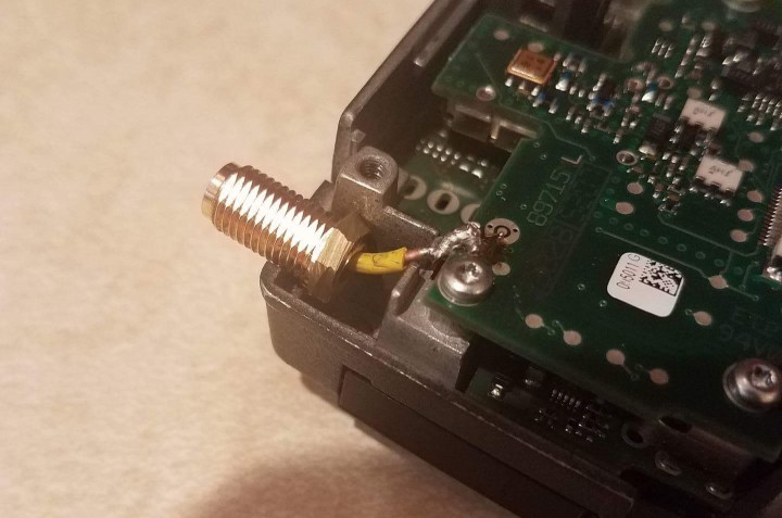
Below is an example of what happens when your wire is too big. There are a couple of other issues with this example. First of all, there is way too much solder. The solder should just be enough to accomplish the mission of bonding the wire to the board. That’s basic soldering and I admittedly messed that up. Second, the heat shrink ends far too early. The inside of the body pack has a metal lip that closes down around where the wire exits that corner area where the connector lives. It does this to isolate the exposed part of the metal where the antenna meets the board. When the body pack closes over this, the wire touches the body and the signal grounds out. The heat shrink should extend as far as possible so that only the tinniest bit of the wire is exposed and can fit into the hole on the board. That way, in theory, the body will only be closing over the heatshrinked portion of the wire.
So beyond those two issues, you can see that the wire is very large. Instead of going coaxial again, I spoke to Andrew Jones and decided to try using a tiny thin steel wire.

I found this to be a much more manageable material for me. And easier to locate. I went over to Lowe’s and bought this for 4 dollars. It fits perfectly into the SMA pin and because of its size and material, it is very easy to shape with tweezers or needle nose pliers. So with these concerns in mind, your end goal should look something like this.
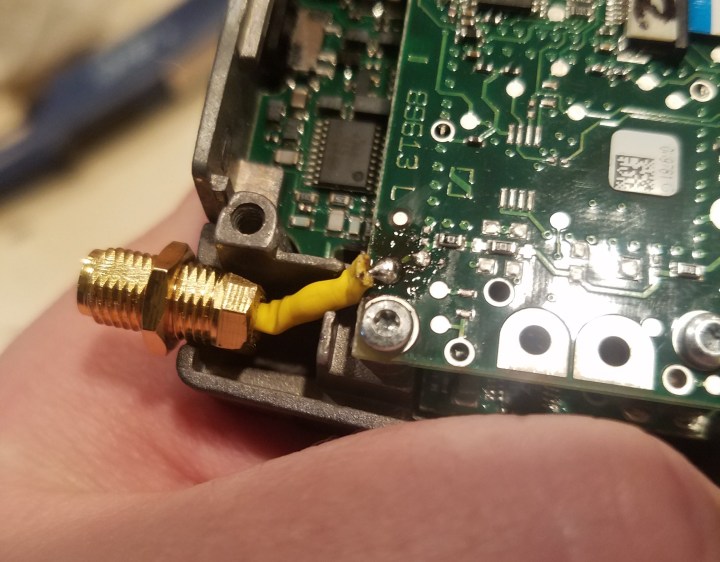
You might notice here how the heat shrink looks to be thick on this wire. That’s because I used two layers just to be safe since the wire is very small and the chassis of the body pack will close down and crimp the cable. This, I have found, is a common area where problems can arise. When the body pack closes up, it gets pretty snug in there and sometimes all that squeezing can actually push the heat shrink to the side or even push through it enough to ground out the wire. The stock antenna’s wire connects at the bottom of the board. This tutorial has the wire connect at the top of the board, so it is more susceptible to crimping of the cable when the body pack closes.
This can occur even a bit after you have successfully completed the mod. I used one body pack for a week with no issues before something happened inside and the wire grounded out. My solution to this was to take a small piece or two of electrical tape and place it across the top of the point where the wire connects to the board. Since that tiny spot has no heat shrink, it is vulnerable to grounding out on the chassis. It is unlikely that your wire will ever ground out if the wire is only exposed at the connection point, but anything can happen with a DIY mod. Some of my body packs had this issue, some did not. Regardless, I recommend doing this on all of them to be safe.
Getting back to the connector, you will notice in the image below that once the back has been sawed off with the dremel, the hole is really tiny.

This is because the connector that I got was for that smaller gauge wire. Now since I was using the tiny steel wire, I figured that this would still be fine. Wrong. With the SMA pin soldered on, and the heat shrink over it, the wire was too thick to fit. And even if it did fit, there is too much metal around the hole. It would likely ground out the signal on the pin. The solution to this is either to buy a new connector with a wider hole (which can take forever to receive, even if you can even find it) or you can attach a drill bit to your dremel and widen the hole. You will want to do this very gently because you can easily destroy or force out the plastic insulator inside of the connector. Every one is different, but just go slowly and carefully until the hole is sufficiently wide and the plastic inside is exposed, but not pushed forward. Once finished, it should look like this.

The SMA pin can now get through and the heat shrink section can fit inside all the way to the plastic. No grounding. These fixes helped me get everything up and running. Now they all work like a charm and it is time to do some comparisons.
I don’t have any actual hard technical data here, but I do have my personal observations. I tested the range of two sets of G3’s. One had only the RX modded (Set A), and the other had both TX and RX modded (Set B). The goal was to see how the range increased with the TX mod. Now just modding the RX produced some ridiculous boosts for me. In the suburbs of Minneapolis, I got literally triple the range of what I got with the stock antennas. Granted this is basically in a vacuum since theres almost no RF traffic in this area. As its been stated over and over, these aren’t Lectrosonics and they can never be Lectrosonics. This is a SMA meant for a RG174. High end sets can deal with heavy RF environments better using true diversity setups and good rejection of competing signals. So take the “triple range” comment with consideration of where you are when you’re using them.
When I compared the two sets, I found that there was only a small difference in range with Set B over Set A. Where I did find a difference was in RF dropouts. With the modded TX, there were significantly fewer clicks and pops when you started to reach the end of the transmitting range. In Set A, as I started to reach the edge of range, there were a lot of pops of static, as well as a low sound of interference and distortion in the signal. In set B, there were nearly no examples of anything bad in the signal. It simply just cut out entirely once I reached the edge of range. (See Andrew’s article about Inverse Square Law)
So my findings seem to suggest that modding the TX (in addition to modding the RX) is most helpful in terms of making the G3’s or G2’s more reliable in maintaining a clean signal.

Jared Elkin is a professional sound mixer located in Minneapolis, Minnesota.
https://www.jaredelkinaudio.com

Might be worthwhile to do the transmitter range testing with a signal strength meter to gather some objective data.
LikeLike