
In Part 1 I walked about how to charge and gather 18650 Li-Ion Cells from cell phone USB batteries. In part 2 I will show you how to mod the very popular 12v Talentcell Lithium battery for use in your audio bag.
Right now if you were to go to the Zoom F8+F4 group on Facebook you would be presented by hundreds of people asking how to power their Zoom recorders. A lot of the comments suggest using the Talentcell 6000mAh battery. I just have 1 massive problem with this suggestion, the Talentcell battery features a nonlocking toggle switch. The last thing you want is to lose power during a recording because something like a cheap toggle switch got flipped. Some people have modded their battery to have a plastic guard over the button. That’s fine but you than have to still deal with the fact that the 2.1mm DC jack doesn’t lock. Here is how you can fix both problems!
Items Needed:
Click the button below for the full Amazon Shopping List
![]()
2.5mm Locking DC Jack – http://amzn.to/2Agh2Ug
1/4″ Fender Washer
2.5mm Locking DC Plug to Hirose Cable – http://amzn.to/2k7Nnqj
12v 6000mAh TalentCell Battery (You want the NON-USB edition) – http://amzn.to/2ngHyYT
18AWG Red/Black wire – http://amzn.to/2AkPGKN
Basic Soldiering Kit w/ Precision Screwdrivers
Small Iron File – http://amzn.to/2AiXtsD
Step 1:
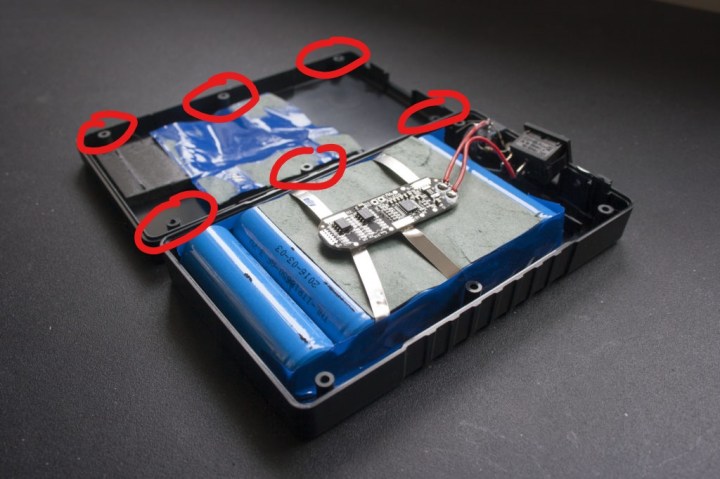
Unscrew the screws holding the clamshell plastic case together.
Step 2:
Use remove the small piece of plastic that is filling the gap in the case where the USB port would be on the upgraded model. File this opening to be bigger till you can slide your 2.5mm Jack into the slot. You will also want to bend the tabs of the DC JACK outwards so they are flat with the back of the jack. This will help it fit without touching the LED Meter PCB. You may want to still put some electric tap on the PCB.
Step 3:
Solder 6-7″ of 18Awg Red/Black wire to the circuit board that is mounted on the 6x 18650 cells. You will solder Red to P+ and Black to P-. Or you could use common sense and match it to the 2 wires already soldered to the BMS circuit. Leave the stock cables in place, you will still be using them along with the original secondary PCB with the big toggle button.

DO NOT LET YOUR SOLDERING IRON CROSS THE PADS BETWEEN P+/P-

Sparks will fly! And if you cross the pads long enough you could do serious damage to your BMS circuit board.
Step 4:
Solder the Red Wire to the center pin of your Locking 2.5MM Jack and the Black wire to the “chassis” pin. In a lot of DC jacks the negative and the ground are connected. You want to select the pin on your connector that is making contact with the side “spring” that touches the outside jacket of the 2.5×5.5mm DC plug. That is a long sentence! Here is a generic DC jack diagram that hopefully makes more sense than I do.
 Step 5:
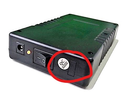
Close it all up. Put your fender washer over your DC Jack and lock it into place using the nut. It will look like this when you’re done. Yes I realize the photo below looks like it is a 1/4″ TS port, but it is not. I’m a sound mixer, not a phone photographer.

So, what have we really done:
The new port we’ve added to the Talent Cell bypasses the toggle switch. We are taking a clean feed directly from the 3S Battery Management System PCB. The 3S BMS handles all the cutoff voltages to protect the 18650 cells from over discharge. It also protects the cells from over charging past 4.2v a cell. So a 3S battery really is 12.6V (3 cells in series) and our 6000mAh is a 2P (2 cells in parallel per series.) This means each cell is 3000mAh each. And while that number is hard to believe, I have seen others run test online and confirm that they hover pretty close to that number. Talentcell produces their own 18650 cells and don’t publish a proper datasheet.
The original 2.1mm non-locking DC jack will still be used for changing just like always. This way when you go to charge the battery you don’t have to buy a new 2.5mm 12.6v Li-Ion charger. If you own a Talentcell you probably never noticed that the charger that came with it is really 12.6 and not 12v. This way it charges the cells all the way up to 4.2v each and not just 4v. By using the original DC jack you still can use the LED battery meter when your charging to know when your battery is full.
 The other big advantage to using a modded Talentcell is you no longer have to use battery cups like you do with the Inspire Energy Battery or NP1 style batteries. A right-angle locking 2.5mm DC jack acts like your battery “cup.” No more accidentally having the NP1 battery jump out of the cup or the cup coming loose off the battery. It’s now locked on!
For the cost of doing one mod you are still coming in less than just one of the 98Wh Inspire Energy Batteries. The Talentcell is not 98Wh though, it’s only 74Wh. But that is more than enough to get the average person who would be doing this DIY project to lunch to swap batteries. I haven’t tried yet to mod the 3000mAh Talentcell yet because the original LED PCB goes from wall to wall internally. But Talentcell does make a 132Wh battery if you really need something that big. I found the 6000mAh pack to be a good size vs weight in my bag. Also the 6000mAh unit is roughly the same size as a Lectrosonics UCR211/411.

What do you about batteries do you want to know more about? Leave a comment below!
Also if you found this article helpful, and maybe I just saved you a few hundred dollars on batteries, help me out. Donate so I can continue to provide articles like this one.
Donation
We offer this content free to everyone. It takes us days to months to research some of these topics. Help us out if you felt this info was helpful to you.
$3.00
 About the Author
Andrew Jones is a location sound mixer based in Los Angeles. He started in the TV and Film industry in 2004. You can email him at Andrew@HoldForSound.com

> So a 3S battery really is 12.6V (3 cells in series)
It’s not really 12.6v except at full charge. The voltage drops as the cell discharges, so cells are rated by their average voltage. These are probably 3.7v batteries, so 3.7 x 3 = 11.1v. But that’s plenty of headroom for the zoom which can take 9-16v. These cells probably bottom out around 3v each. I set the cutoff for my zoom at 9.5v, as I don’t want to hit the bottom, plus I want an audible warning before approaching the built-in hard cutoff.
The 12.6v charger will max the batteries to their 4.2v fully-charged voltage.
I like the idea of using the cheaper non-usb batteries… that gives a lot more room to work with on the top! But I love the USB for plugging in a gooseneck light, which gets around the problem I posted about not having a backlit stop button.
LikeLike
So the battery cut off is 3.2v per cell or 9.6v for the pack. If you use the USB pack there’s no room for the 2.5mm DC jack.
LikeLike
I use the Talent bat. of 11000 mah . With 12 v. There are special bags for Lithium batteries that protect fire and explosion , they use very secure tight Velcro. I keep mine located in the back pocket of the Petrolbag, it works without any problem.
This envelope cost $12 dollars and they are really good.
LikeLike
Is there a way to bypass the 3A output limit as well?
LikeLike
So the mod does that too. The 22awg wire I used it rated for 7A but even the biggest sound bags I’ve seen would be hard pressed to need more than 3A.
LikeLike
I see! I don’t understand how though, I thought you were just bypassing the switch.
LikeLike
The PCB board that host the switch is the bottle neck for the amps. You can run 7amps on the PCB trace lines.
LikeLike
I see, now I understand. That also means I lose the 12v regulation then.
LikeLike
It doesn’t do 12v regulations. It always does 12.6 voltage and drops over time
LikeLike
Sadly this DIY will no longer work because on the new ones they have decided to PCB the entire power/switch interface, thus making it impossible to remove the old DC jack 😦
LikeLike
You’re saying the BMS and power switch are now the same PCB?
LikeLike
I just got a new Talentcell and it’s as Jared stated, so not enough clearance to put the locking DC plug in where the USB plastic bit is located. You could always drill a hole in the side to mount the threaded output but there’s no obvious connection to make except to the existing output jack, which still leaves the switch in the path.
LikeLike
P.S. I guess you could just tap off the posts of the switch, though I’d have to make sure I knew which was + and -.
LikeLike
This
Is probably a better choice, especially if you are splitting power off as I am to the F4 and MixPre.
Cheaper anyway…
Good content
LikeLike
I just received the current model. It’s true there is a secondary PCB for the switch, DC jack, USB connector, and a new 5 LED battery indicator. The original PCB on the battery pack is the same. The layout and spacing appears the same as the pictures here, so I believe you could simply cut down the part of the PCB where the USB connector would mount and follow this plan. A little more difficult, but not impossible.
LikeLike
Hi Andrew,
Are you powering all bag (zoom f8 and three lectros) with one Talentcell 6000mAh battery? How long it is last? All day, half day?)
LikeLike