Adding a SMA port to a Sennheiser G2/G3 is one of the most lusted after mod’s in the world of TV Film audio.The Sennheiser G2/G3 EW100/EW300 features a fixed VERY flexible antenna that goes limp after a few months of use. This antenna also makes them a pain to store in cases between uses.
Lets get one thing out of the way, adding a SMA antenna does not make them Lectrosonics; it will not transmit magically across a football stadium; the output is still 30mw. The SMA mod offers a lot of benefits to the G3 though. Once modded the Sennheiser units are more stable with less RF drop outs, storage between uses is easier. You can now use a MultiRF with a “Shark Fin” Log Periodic directional antenna, adding a booster to to increase the RX’s signal. It also just looks cooler!
Supplies:
Sennheiser G2/3 body pack unit
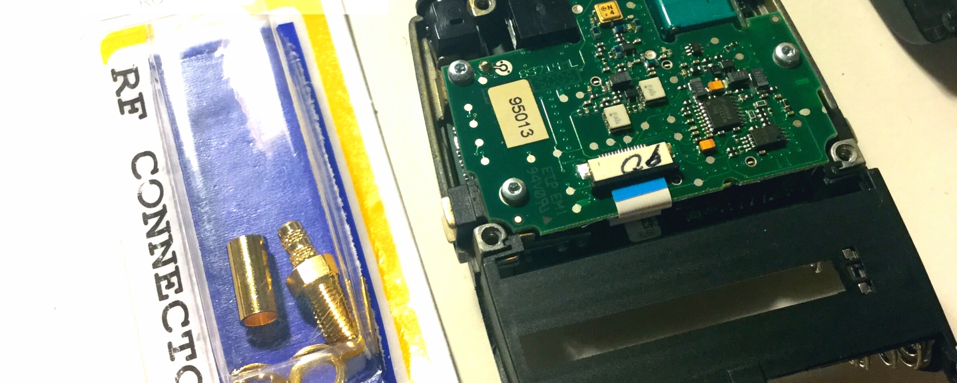
SMA Female connector
Dremel rotatory saw
Vice clamps
1/8″ Heat shrink
50 ohm solid coax wire ( OR tiny gauge steel wire)
Soldering iron
Tweezers
Hex Key set
Remote Audio SMA stiff antenna
STEP 1:
Open the unit by removing the battery door and flipping it on it’s face and unscrewing the 4 Hex screws on the back of the unit.

STEP 2:
Unscrew the 3 screws holding the transmitting PCB in place. Note that the two lower screws have more threads and should be separated so they go back in the right place. The top screw matches the threading of the 4 screws that held the unit together.

STEP 3:
Don’t worry about the ribbon cable. Use your tweezers to grab the old pin holding the antenna to the PCB. Use your soldering iron to melt the solder; tug on the old antenna while the solder is melted and it will pop right out.

STEP 4:
Now let’s concentrate on modding the SMA connector to fit in the G2/3 antenna slot. Natively it is too wide so two sides need to be grinded off using the Dremel mounted with the cutting disk. Use the vice clamp to hold the unit by the “cable side” of the connector like in the photo below. DO NOT CLAMP OR GRIND ON THE SMA THREADS!!!! Clamping onto the threads will destroy them.

STEP 5:
Now hold it by the newly grinder flat sides and cut off he cable side of he connector so it looks like this. AGAIN do not clamp onto he threaded SMA side.

The flatter you can make this hole, the easier it will be to force your 50 Ohm cable through the hole.
STEP 6:
Solder the tip of your 50 Ohm Coax cable to the SMA pin. Slide your 1/8″ heat shrink up to the end of the pin. Use the photo for reference, your pin may be different depending on which connector you buy and which ype of SMA you plan on going too.

STEP 7:
Shove it in the back of the hole on the SMA connector. It should look identical to the photo below. You want to make sure no metal from the 50 Ohm cable is touching the outside housing of the connector. This is where extra heat shrink may be needed.

STEP 8:
Now solder the connector to he hole here the old antenna lived on he PCB.

STEP 9:
Replace all the screws on the PCB, keeping the finer headed screws back into the bottom and the course screws into the top mounting hole. now replace the four course hex screws into the back of he unit.
Locate the lock washer and the nut that screws down the SMA threads.

Screw it on. Use the vice clamps to really add the torque needed to get the lock washer to bite into the G3 housing. You are now done!

Now follow the instructions on the Remote Audio SMA antenna packaging so you know where to cut the antenna to match your frequency block.
Another of our writers wrote up his experiences with this tutorial and how he troubleshooted the mod. He also discussed the results when only modding the reciever.

About the Author
Andrew Jones is a location sound mixer based in Los Angeles. He started in the TV and Film industry in 2004. You can email him at Andrew@HoldForSound.com

Whilst this mod has been available in the UK for may years I must congratulate you on a really clear & concise set of instructions.
LikeLike
Typically transmitter transmit antennas are checked with SWR (standing wave ratio) meters to make sure the antenna length is correct and so the signal goes out into the air and is not reflected back into the transmitter. Not so important for receivers. Where does the length of the transmit antenna begin and where does it end for measurement and cutting purposes?
LikeLike
When you buy a Remote Audio Stiff whip, it features a cut guide based on Lectrosonic Blocks. For Sennheiser Band A, cut between Block 20 and 21.
LikeLike
What would you recommend for band B? The frequencies on the Remote Audio cutting guide suggest cutting between 24 -26 but the antenna already on the G3 receiver is much shorter than that…
LikeLike
Thank you so much for this. I am having a challenge finding what exact SMA connector you used? It would be amazing if you could drop a link.
LikeLike
I want connect G3 with booster and antenna sennheiser A2003UHF. How can I do, because booster need power 10v-18v? Thank!
LikeLike
A sma to bnc cable will let you hook it up. As for adding a booster, you’ll only do that if you have a long bnc run between your receiver and the antenna. As for where to get 10v-18v, any audio bag will be powered off such voltagem
LikeLike
Thank! Exactly how do I do it? Can I connect Ant Reiceiver G3 – spliter ASA1 – booster – ant A2003UHF? ASA1 use DC 12V out for booster. 8 reiceiver 112 G3 can connect with 1 ASA1. But ant out of ASA1 have DC out for reiceiver 100G3. So it make electric shock for 112G3, isn’t it? Thank!
LikeLike
I don’t know. My antenna system is all passive bc I have short BNC cables. Sounds like a question for Facebook or JWSound Forum.
LikeLike
Hello, Can I change a sma female connector for a BNC female connector? And off course use a Remote audio bnc connector. Here in Peru I cant find a sma connectors.
thanks
sebastian
LikeLike
Maybe? Youd need to dremel the housing of thr G2/3 and someone fit the backside of a BNC connector into the body of the reciever… idk
LikeLike
hey andrew,
what exact sma connector did you use? I’m feeling a bit lost in all the variaties
thanks
LikeLike
Bingfu SMA Bulkhead Jack Standard 50 ohms RF Connector for 195 RG58 RG400 Coaxial Cable Mounting on Modem Radio Antenna(Pack of 2) https://www.amazon.com/dp/B00X9IPE1K/ref=cm_sw_r_cp_apa_MvlczbMM5V5H5
LikeLike
Another quick question: What diameter is the coax cable you used?
LikeLike
Yes what diameter is the cable?
LikeLike
I just fried a G3 receiver 😦 No RF whatsoever now, tried going back to stock antenna with no luck. Be careful out there folks!
LikeLike
I’ve done it using a 1 mm section, nickel-titanium wire as the antenna, and a common 2 cm, 0,5 mm copper wire to connect the sma female to the board, I am comparing this receiver with another one with the standard antenna. The standard is more stable, less susceptible of drops when I hold the antenna with hand and make other movements.
can the copper wire be the weak point of this?
LikeLike
Hello. Thank you for such a great info. Is there a chance to send my G3’s to someone to add SMA mods? I dnt like to do it myself since I don’t have experience.
LikeLike
Absolutely! Reach out via the contact page and we can help you out!
LikeLike
Just ordered everything to attempt this mod. My G3’s are going strong, minus beat up antennas. Found panel mount SMA connectors on Amazon that should avoid the issue of trimming the “crimp” section of each and have a solder terminal: https://www.amazon.com/dp/B078H4F8R6?psc=1&smid=A1TE63QTMAEOQO
LikeLike